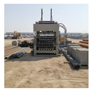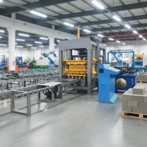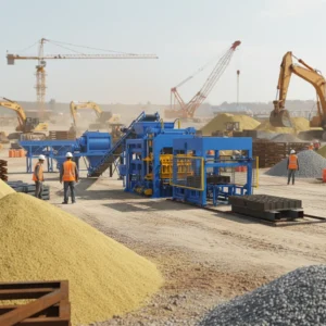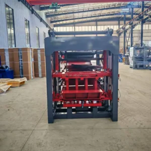
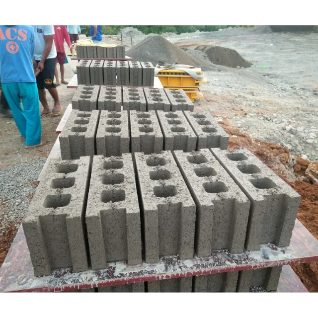
System-Level Synchronization — The QT5-15 line is specified as a coordinated sequence of stations, where the mixer discharge, pallet feeder, press cycle, and stacking mechanism are all timed to prevent idle gaps during continuous production.
Technical Specifications
| Parameter | Value |
|---|---|
| Model | QT5-15 |
| Product Type | Hydraulic Hollow Block Making Machine |
| Overall Dimensions (L×W×H) | 7400×1950×2800 mm |
| Vibration Frequency | 0–60 Hz |
| Vibration Form | Platform Vibration |
| Vibration Force | 80 kN |
| Moulding Mode | Automatic loading with vibration moulding |
| Pallet Size | 1100×550 mm |
| Molding Cycle | 15–20 s (basis not stated in source — confirm block format / material / thickness) |
| Overall Power | 32 kW |
| Total Mass | 5000 kg |
| Demolding Method | Hydraulic |
| Recommended Factory Area | 1000 m² |
| Control System | PLC (Programmable Logic Controller) with touch screen interface |
| Hydraulic System | Independent integrated hydraulic station |
| Output Capacity (Hollow Block 400×200×200 mm) | 900–1200 pcs/h, 7200–9600 pcs per 8 hr shift (5 pcs per mould, 15–20 s cycle) |
| Output Capacity (Hollow Block 400×150×200 mm) | 1080–1440 pcs/h, 8640–11520 pcs per 8 hr shift (6 pcs per mould, 15–20 s cycle) |
| Output Capacity (Solid Brick 240×115×53 mm) | 5760–7680 pcs/h, 46080–61440 pcs per 8 hr shift (32 pcs per mould, 15–20 s cycle) |
| Output Capacity (Rectangular Paver 200×100×60 mm) | 3600–4500 pcs/h, 28800–36000 pcs per 8 hr shift (25 pcs per mould, 20–25 s cycle) |
| Output Capacity (Zigzag Paver 225×112.5×60 mm) | 2304–2880 pcs/h, 18432–23040 pcs per 8 hr shift (16 pcs per mould, 20–25 s cycle) |
| Raw Material Compatibility | Fly ash (up to 70%), slag, gangue, sand, crushed stone, cement, water |
| Block Compressive Strength | >15 MPa |
| Automation Level | Automatic (pallet feeding, material feeding, vibrating, demoulding) |
| Assembly State | Fully assembled with pallet feed machine, block making machine, storage hopper, conveyor, hydraulic unit, PLC control cabinet |
Application Suitability
| Application | Material or Output |
|---|---|
| Hollow Block Production Plants | Crushed stone, sand, cement, and industrial residues like fly ash (up to 70%) |
| Solid Brick Manufacturing | Standard concrete mixes for high-volume structural brick formats |
| Paving Block and Interlocking Brick Production | High-density aggregates and pigmented face mixes for 60–80 mm pavers |
| Fly Ash and Industrial Residue Utilization Projects | High-volume consumption of fly ash, slag, and gangue for eco-building materials |
| On-Site Block Production for Construction Contractors | Local sand and aggregate processed directly at the project footprint |
| Environmental Protection Building Material Production | Recycled construction waste and industrial by-products in structural blocks |
Why the Mixer Discharge Rate Defines Your Actual Output
A block machine can only press as fast as the upstream stations can deliver material and the downstream stations can clear pallets.
When you look at the quoted capacity for a QT5-15 block machine production line, the figures assume a perfect rhythm between every station. If the mixer takes 90 seconds to prepare a batch but the press completes a cycle every 15 seconds, the host machine will sit idle waiting for material. This synchronization gap is where daily output quietly disappears, often without triggering a single alarm on the control panel [NEED_CITE: industrial line balancing and bottleneck analysis].
Coordinating the QT5-15 Block Machine Production Line Stations
The raw material feeding, mixing, and pallet handling systems must be calibrated to the 15–20 second moulding window. When the storage hopper and conveyor deliver a consistent feed to the mould box, the platform vibration can achieve full compaction without extending the cycle to compensate for lean mixes. The line layout must position the mixer discharge and the pallet feeder at distances that allow continuous transit without the press waiting on either station.
Managing the Flow From the Press to the Curing Yard
Once the hydraulic system demoulds the block, the pallet carrying the wet product must move immediately to the stacking or curing rack area. If the discharge conveyor is too slow, the next loaded pallet cannot enter the press, creating a backup. The 1100×550 mm pallet dimension is chosen specifically to align with standard curing rack slots and forklift tine spacing, ensuring that the transfer from the QT5-15 block machine production line to the curing yard does not require manual repositioning [NEED_CITE: material handling and pallet standardization in concrete plants].
Interpreting the Vibration and Hydraulic Specifications
The 80 kN vibration force operating at 0–60 Hz is applied through platform vibration, which compacts the aggregate from the base of the mould upward. This force must be balanced with the independent integrated hydraulic station that controls the head pressure during the moulding cycle. When these two systems are correctly phased, the resulting block achieves a compressive strength exceeding 15 MPa without cracking the green product during demoulding. The PLC touch screen interface manages this sequence, ensuring that the vibration duration and hydraulic pressure application are repeatable across thousands of cycles per shift.
The Cost of Ignoring Line-Wide Cycle Times
If the supporting equipment is sourced separately without a unified timing plan, the press will frequently pause while the conveyor clears or the mixer finishes a batch. These micro-stops accumulate across an eight-hour shift, reducing the daily yield significantly below the theoretical calculation. Furthermore, if the pallet material and thickness are not specified to handle the repeated impact of the 80 kN vibration, premature pallet failure introduces unplanned downtime and disrupts the stacking sequence [NEED_CITE: impact of pallet degradation on block machine uptime].
Why Sourcing the Complete System Matters
- Unified Timing: The raw material feeding, mixing, and pallet stations are mapped against the press cycle so no single station forces the host to idle.
- Mix-Specific Configuration: The equipment is configured around the buyer’s actual aggregate and target block format, rather than a generic catalogue default.
- Pallet and Rack Matching: The 1100×550 mm pallet specification is integrated with the curing rack and forklift systems already present in the 1000 m² plant layout.
- Automation Scalability: The line supports starting with core automatic functions and adding further handling automation as production volume grows.
Documentation & Verification
- Line layout drawing showing cycle time per station and material flow paths for the specific block format selected
- Capacity calculation document stating output per specific block format based on the buyer’s mould selection
- Pallet specification sheet detailing size, material, and thickness matched to the curing area and forklift capacity
- Voltage, frequency, and PLC display language confirmation document signed before production begins
- Factory test record demonstrating the synchronized cycle sequence using the buyer’s specified mix design
- Hydraulic and electrical schematic showing the independent station separation and PLC wiring logic
Installation, Commissioning & Support
- Foundation requirements for the 7400×1950 mm footprint and the 32 kW power supply with dedicated circuit breakers
- On-site assembly of the fully shipped pallet feed machine, press, storage hopper, and conveyor sections
- Calibration of the PLC touch screen interface to the local voltage and frequency before the first production run
- Operator training covering the quick mould change procedure and the synchronized start-up sequence across all stations
- Spare parts list for the hydraulic seals and vibration components specific to the 80 kN platform system
- Maintenance schedule for the independent integrated hydraulic station to protect it from dust and vibration damage
Preparing Your Inquiry for a Balanced Line
To ensure the QT5-15 block machine production line is configured without bottlenecks, please provide the specific block formats you intend to produce, your target daily output per format, and the dimensions of your available factory floor. We also need to know the local voltage and frequency, your preferred PLC language, and the specifications of the raw materials you will source locally.
Frequently Asked Questions
Q: How is the line capacity calculated, and which block format is assumed?
A: The capacity figures are specific to the block format, mould cavity count, and cycle time. For example, the 900–1200 pcs/h figure applies to a 400×200×200 mm hollow block with 5 cavities and a 15–20 second cycle. We provide a detailed capacity calculation for your specific format selection, ensuring the mixer and stacker are sized to match that exact rate.
Q: What supporting equipment is included, and where are cycle times balanced?
A: The line includes the raw material batching, mixer, conveyor, pallet feeder, the QT5-15 press, and the discharge system. We calculate the transit time for the conveyor and the mixing time for the batcher to ensure they align with the press cycle. If one station is naturally slower, the line layout is adjusted to include buffer space or a higher-capacity unit to prevent the press from waiting.
Q: How is the pallet size matched to the curing rack and forklift on site?
A: The 1100×550 mm pallet is a standard size chosen to fit conventional curing rack slots and standard forklift tines. Before shipment, we confirm your existing curing yard dimensions and forklift specifications. If your site uses a non-standard racking system, the pallet size and the discharge conveyor width can be adjusted to ensure smooth transfer without manual handling.
Q: What voltage, frequency, and PLC language configuration is confirmed before shipment?
A: We require the buyer’s site electrical specifications and the preferred language for the touch screen interface before production begins. This ensures the motors, the independent hydraulic station, and the PLC are wired and programmed correctly for the destination country. This verification prevents commissioning delays that often occur when control components arrive with the wrong regional settings.