
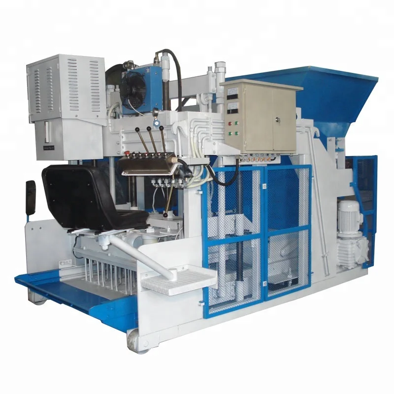
Configuration Matched to Site Reality — the QMY12-15 mobile egg laying block machine is specified alongside mixer feed rate, curing area layout, and power supply so upstream equipment never forces the press into idle cycles.
Technical Specifications
| Parameter | Value |
|---|---|
| Model | QMY12-15 |
| Product Type | Mobile Egg Laying Block Making Machine |
| Overall Dimensions (L×W×H) | 3250×2100×2300 mm |
| Total Mass | 4200 kg |
| Total Power | 16 kW |
| Hydraulic System Pressure | 16–20 MPa |
| Excitation Frequency | 3200 Hz |
| Vibration Mode | Three-dimensional mold vibration |
| Demold Method | Hydraulic |
| Turning Method | Hydraulic |
| Moving Method | Automatic movement with hydraulic steering |
| Molding Cycle | 10–15 s (basis not stated in source — confirm block format and material) |
| Output Capacity | 2880 pcs/h for 400×200×200 mm hollow brick (basis not stated in source — confirm actual cycle per format) |
| Mould Format Example | 12 pcs/mold (400×200×200 mm hollow block) |
| Raw Materials | Fly ash, cinder, coal gangue, river sand, gravel, cement, industrial waste residue |
| Block Formats Supported | Hollow block, porous brick, road kerb, road brick, grassing brick (by changing moulds) |
| Control System | Computer automatic control (PLC type and brand to be confirmed) |
| Voltage & Frequency | Configurable — confirm before production |
| PLC Display Language | Configurable — confirm before production |
| Automation Level | Semi-automatic with automatic movement and hydraulic steering |
| Warranty | 1 year for the whole machine (excluding spare parts) |
Application Suitability
| Application | Material or Output |
|---|---|
| On-site hollow block production at housing projects | Fly ash, river sand, gravel, and cement mixes |
| Road kerb and paving brick laying at infrastructure sites | Crushed stone, cinder, and cement aggregates |
| Porous brick and grassing brick for landscaping contracts | Coal gangue, sand, and industrial waste residue blends |
| Remote or temporary block production for development contractors | Local aggregate with cement binder, ground-laying without fixed plant |
What "Pieces per Hour" Hides From the Site Manager
Output figures only mean something when the block format, mix design, and upstream feed cycle are all named alongside them.
When a mobile block machine production line is quoted with a single hourly number, that number almost always assumes one specific hollow block size running on a standard sand mix. On an actual project site where the aggregate is local laterite or the target product shifts between kerbstones and porous bricks, the real daily output drops noticeably below the quoted figure. The mixer batch size, conveyor feed rate, and curing area travel path must all match the press cycle for each format — otherwise the machine sits waiting for material or the freshly laid blocks get driven over before they cure. [NEED_CITE: mobile block production cycle matching across equipment stations]
Upstream Feeding and Mixing Must Track the Press Cycle
The QMY12-15 completes a molding cycle in the range of 10–15 seconds, but that window shifts depending on block thickness and material viscosity. A mixer that discharges every 30 seconds will starve the press when it runs smaller solid formats, and a mixer that discharges every 90 seconds will leave the press idle when it runs 400×200×200 mm hollow blocks. The mobile block machine production line only reaches its stated throughput when the raw material feeding station and mixer batch size are calculated against the specific format the buyer plans to produce most often.
Curing Area Layout and Hydraulic Steering Coordination
The machine moves automatically with hydraulic steering across the curing ground, laying blocks in continuous rows. The curing area must be dimensioned so the machine completes a full pass before the earliest blocks are ready for collection — if the area is too short, the steering path forces tight turns that crack freshly demolded units. Planning the curing area length and forklift access lanes around the travel speed of the egg laying block machine supporting equipment prevents bottlenecks that no amount of press speed can overcome. [NEED_CITE: site layout planning for mobile egg laying block production]
Reading the Specs That Shape On-Site Output
The hydraulic system pressure of 16–20 MPa works together with the three-dimensional mold vibration at 3200 Hz to compact the mix into dense, structurally sound blocks. On a local laterite or high-clay aggregate, higher hydraulic pressure may be needed to achieve the same compressive strength that a clean river sand mix reaches at the lower end of the pressure range. The total power draw of 16 kW covers the press, vibration, and hydraulic steering motors; the on-site generator must also supply the mixer and any conveyor feeding the hopper, so sizing the power source for the entire line avoids voltage drops that stall mid-cycle. Multiple mould formats — hollow block, porous brick, kerb, paving, and grassing brick — each change the cycle time, and the upstream equipment must be adjusted accordingly every time the mould is swapped.
The Cost of Skipping the Line-Level Match
Buyers who specify the press alone and source the mixer and material handling locally often discover that mismatched feed rates create a cascade of idle time. The press waits for the next batch, operators stand by, and the daily block count falls well below what the cycle time suggested. On remote project sites where fuel and labour costs are already elevated, this mismatch compounds across the entire project timeline. [NEED_CITE: equipment mismatch impact on remote construction site productivity]
Why Source the Full Line Together
Block machinery is our single focus, so the press, mould, pallet, and handling equipment are specified as one matched system rather than assembled from separate suppliers. Configuration is set against the buyer’s actual mix design and local aggregate — not a catalogue default that assumes standard sand. Mould design covers the formats the buyer’s market actually sells, including custom drawings when the project calls for a non-standard kerb or interlocking profile. The automation level is selectable, allowing a contractor to start with semi-automatic operation and add handling equipment later. Installation support includes operator training on-site so the crew can run the line independently from the first production day.
Documentation & Verification
- Line layout drawing showing mixer, feeding station, and curing area dimensions matched to QMY12-15 travel path
- Capacity calculation sheet stating block format and cycle time assumed for each output figure
- Voltage, frequency, and PLC display language confirmation form signed before production
- Hydraulic and electrical schematic for on-site troubleshooting during remote project operation
- Factory test record on buyer’s specified block format and mix before dispatch
Installation, Commissioning & Support
- Ground leveling and curing area preparation guidance based on 3250×2100×2300 mm machine footprint
- Power supply circuit sized for 16 kW total draw plus mixer and conveyor load
- Hydraulic steering calibration and travel path setup during on-site commissioning
- Operator training covering mould change procedure across hollow, kerb, and paving formats
- Wear parts and mould list supplied at delivery for first replacement on remote sites
Planning the Right Line Configuration
To size the upstream and handling equipment correctly, share your target block format, local raw material type with a sample photo, daily output requirement, and on-site curing area dimensions. Include your available voltage, frequency, and preferred PLC display language so the control system ships ready for immediate commissioning.
Frequently Asked Questions
Q: How is output capacity calculated per block format, and what upstream equipment must match?
A: Each output figure is based on a specific block size and cycle time. The mixer batch size and feed interval must align with the press cycle for that format — faster formats need a larger or more frequent mixer discharge, while thicker formats allow longer feed intervals. Line capacity is only meaningful when the format is stated.
Q: What raw material feeding and mixing setup keeps the QMY12-15 running without idle time?
A: The mixer output rate and hopper feed conveyor must deliver a fresh batch within the molding cycle window. For the QMY12-15, we match the mixer drum capacity and discharge timing to your primary block format so material arrives before the press completes each cycle.
Q: How should the curing area be planned around the machine’s movement?
A: The curing ground must be long enough for the hydraulic steering system to lay a full row before looping back. Forklift lanes need clearance alongside the block rows so collection does not interrupt the machine’s automatic travel path during active production hours.
Q: What electrical confirmations are needed before shipping to an overseas site?
A: Voltage, frequency, and PLC display language must be confirmed before production begins. This ensures the control panel matches local power standards and the operator interface is readable on arrival, avoiding commissioning delays at the project site.
Q: Which moulds and spare parts should be included in the initial order?
A: For remote on-site operations, we recommend ordering the full set of planned block moulds plus a wear parts kit covering hydraulic seals, vibration springs, and mould liners. This ensures the first replacement cycle does not halt production while waiting for international shipping.


