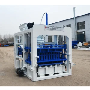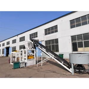
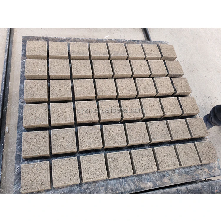
Stationary block machine production line synchronization — every station from raw material feed through to the discharge end is configured around the QTF3-20 press cycle so the mixer, feeder, and pallet conveyor all arrive at the same rhythm without waiting or piling up.
Technical Specifications
| Parameter | Value |
|---|---|
| Model | QTF3-20 |
| Product Type | Stationary Hydraulic Block Making Machine |
| Overall Dimensions (L×W×H) | 4000×3500×2300 mm |
| Total Mass | 2870 kg |
| Total Power | 17.5 kW |
| Vibration Form | Platform Vibration |
| Drive System | Hydraulic system with proximity switch monitoring |
| Control System | Semi-Automatic |
| Feeding System | Double layer (raw material and color surface material) |
| Frame Structure | #12 U-bar welding, overall frame structure |
| Line Configuration | Forms line with JQ350 mixer and 8m belt conveyor |
| Raw Material Compatibility | Cement, Sand, Fly Ash, Coarse aggregate, Slag |
| Output Capacity | 4320 pcs/day (basis not stated in source) |
Application Suitability
| Application | Material or Output |
|---|---|
| Hollow block production for load-bearing walls | Cement, sand, and coarse aggregate blends |
| Interlocking paver and color face brick | Double-layer feeding with pigmented surface mix |
| Grass brick and slope protection units | Porous concrete mixes with high coarse aggregate ratio |
| Standard solid bricks for masonry | Fly ash and slag blends with standard cement content |
When the Pallet Conveyor Becomes the Bottleneck
A stationary block machine production line only moves as fast as its slowest station, and the discharge end is where mismatches surface first.
Green blocks pile up at the press exit the moment the pallet conveyor or stacker cannot keep pace with the cycle.
I have watched plants in West Africa run the press at full speed for two hours, then shut down because cracked blocks stacked three layers deep at the discharge end. The QTF3-20 completes its hydraulic press and vibration cycle in a fixed window. If the pallet return conveyor or block stacker operates on a longer interval, the press sits idle or ejects onto an occupied pallet. Every supporting station must be timed against the press cycle before the line is assembled, not after [NEED_CITE: block plant station cycle synchronization practices].
Matching the Mixer and Feeder to the Press Cycle
The JQ350 mixer paired with the 8-meter belt conveyor must deliver a fresh batch to the QTF3-20 hopper before the current charge is exhausted. Double-layer feeding adds a second pass for the color surface material, extending the feed station dwell time. If the mixer discharge interval exceeds the press cycle, the hopper runs dry mid-cycle and the resulting blocks show inconsistent density at the core. The stationary block machine production line specification must state the mixer batch time against the press cycle so the feeder never starves.
Pallet Size, Curing Area, and Forklift Alignment
Pallets travel from the press to the curing rack, and their dimensions must match three constraints simultaneously: the QTF3-20 platform size, the curing rack slot width, and the forklift tine spacing already on site. A pallet chosen only for the press platform will jam in the curing rack or require a different forklift, adding handling steps that were never in the layout plan. The pallet specification should be locked against the buyer’s existing curing infrastructure before the line ships [NEED_CITE: pallet dimension standards in concrete block production].
How Hydraulic Pressure and Vibration Determine Block Density
The QTF3-20 uses platform vibration synchronized with hydraulic pressure through proximity switch monitoring. The hydraulic ram applies vertical compaction while the vibrating platform settles the aggregate into voids. If vibration force is too low for a stiff mix with high coarse aggregate, blocks emerge with porous cores and fail compressive strength tests. If vibration is too high for a wet fly ash mix, the material liquefies and blocks slump before curing. The proximity switches confirm that each station — feed, press, eject — completes before the next begins, preventing partial cycles that produce undersized units.
The Hidden Cost of Skipping the Line Layout
Quoting the press alone without specifying the mixer capacity, conveyor length, and pallet handling system leaves gaps that surface during commissioning. A mixer that batches too slowly forces the press into standby cycles. A pallet return belt that runs too fast scuffs wet blocks off the pallet edge. Each mismatch means the plant runs below the capacity the buyer budgeted for, and the gaps only become visible once concrete is flowing through the system [NEED_CITE: concrete block plant commissioning failure modes].
Why Specify the Full Line Through One Supplier
- Block machinery is the sole product focus, so the QTF3-20 press, JQ350 mixer, and 8m conveyor are configured as one matched set rather than assembled from separate vendors.
- Line layout and capacity calculation state the block format assumed, so the buyer knows which product the daily output figure refers to.
- Pallet size and material are selected against the buyer’s curing area dimensions and forklift capacity, not chosen from a catalogue default.
- Voltage, frequency, and control display language are confirmed before production begins, preventing wiring rework and PLC reprogramming on site.
- Factory testing runs the full station sequence — feed, press, eject, pallet return — so cycle synchronization is verified before the line is crated.
Documentation & Verification
- Line layout drawing showing station spacing and pallet flow path for the QTF3-20 configuration
- Capacity calculation sheet stating the block format and mix assumed for output figures
- Hydraulic and electrical schematic with station-by-station power draw and cycle timing
- Voltage, frequency, and PLC display language confirmation record before production
- Factory test record running the full feed-press-eject sequence before dispatch
Installation, Commissioning & Support
- Foundation plan sized for the QTF3-20 footprint of 4000×3500 mm and 2870 kg mass
- Dedicated 17.5 kW power circuit with voltage and frequency matched to local grid
- JQ350 mixer and 8m belt conveyor assembled and aligned to the press feed height on site
- Proximity switch calibration to synchronize feeder, press, and pallet conveyor cycles
- Operator training covering double-layer feeding sequence and mould change procedure
- Wear parts list identifying hydraulic seals and vibration platform consumables
Before You Request a Quote
Tell us which block format sells in your market and what daily volume you need, so the stationary block machine production line is sized to your actual product, not a catalogue default. Share your available raw materials and their source, the curing area dimensions you plan to use, and the local voltage and frequency so the electrical system is built right the first time.
Frequently Asked Questions
Q: How is the daily output figure for the QTF3-20 verified?
A: Output depends entirely on the block format, wall thickness, and mix design used. A hollow block with thicker walls requires longer vibration and compaction time per cycle than a standard paver, changing the daily total. We state the assumed format and mix alongside any capacity number so buyers compare real production scenarios, not abstract press speed.
Q: What supporting equipment comes with the line quotation?
A: The standard configuration includes the JQ350 mixer, 8-meter belt conveyor, and the QTF3-20 press with its hydraulic and electrical systems. Pallet handling, stacking, and curing rack equipment can be added to the scope. We specify each station in the layout drawing so nothing is left to source separately after installation.
Q: How do station cycle times stay synchronized?
A: Each station — mixer discharge, belt conveyor delivery, double-layer feeding, hydraulic press, and pallet return — is timed against the QTF3-20 cycle using proximity switch monitoring. If one station finishes early, it waits on signal rather than pushing material into a press that is still compacting. This prevents partial cycles and idle gaps.
Q: What electrical details are confirmed before production?
A: We confirm the site voltage, frequency, and required PLC display language before the electrical panel is built. This avoids motor rewiring and control reprogramming when the line arrives. The hydraulic and electrical schematic shows each station’s power draw so the buyer can prepare the correct supply circuit in advance.
Q: Can the line start semi-automatic and add automation later?
A: The QTF3-20 control system is semi-automatic, and the line layout leaves physical space and electrical capacity for automatic stackers and pallet return conveyors to be added later. The upgrade path is defined in the initial layout so foundation work and cable routing accommodate the expansion without rebuilding existing stations.