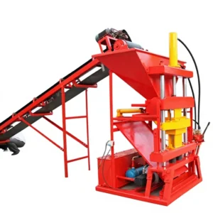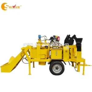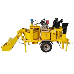
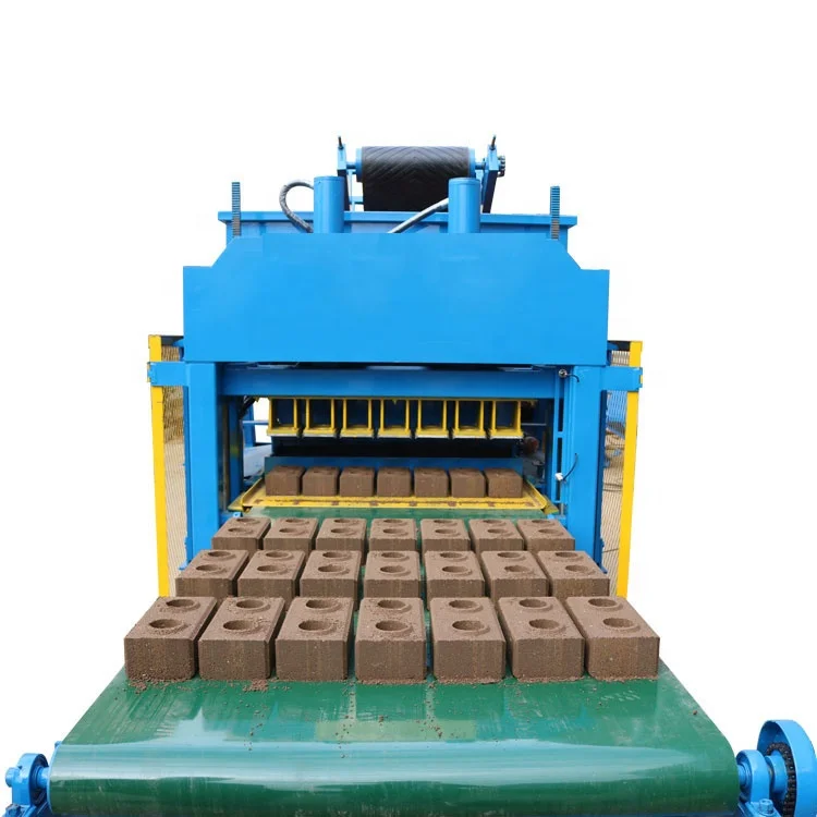
Matched Line Flow — every upstream feeder and downstream handler is timed against the LY7-10 press cycle so no station starves the press or piles up unhandled output.
Technical Specifications
| Parameter | Value |
|---|---|
| Model | LY7-10 |
| Product Type | Automatic Clay Interlocking Brick Making Machine |
| Rated Power | 18.5 kW |
| Overall Dimensions (L×W×H) | 2260 × 1500 × 2380 mm |
| Net Weight | 1600 kg |
| Hydraulic Pressure | 25–32.5 MPa |
| Molding Cycle | 10–15 s |
| Output Capacity | 20,160 pcs/day (based on 300×150×100 mm interlocking brick, 7 pcs/mould) |
| Pcs per Mould | 7 (300×150×100 mm format) |
| Pcs per Hour | 2,520 (based on 300×150×100 mm interlocking brick) |
| Raw Materials | Laterite, yellow or red soil, sand, cement, water |
| Worker Requirement | 1–2 workers |
| Automation Level | Automatic (material feeding, mould pressing, mould lifting) |
| Control System | Confirm PLC type, brand and display language before order |
| Voltage & Frequency | Confirm before order |
| Vibration Force | Confirm kN rating before order |
| Pallet Size | Confirm dimension and material before order |
| Mould Change Time | Confirm before order |
| Stacking Method | Confirm manual or automatic before order |
Application Suitability
| Application | Material or Output |
|---|---|
| Clay interlocking brick plant | Laterite or red/yellow soil blended with 6–8 % cement |
| On-site housing project brick production | Local soil and cement mixed to match site consumption rate |
| Building material distributor adding interlocking format | 300×150×100 mm interlocking bricks alongside existing product range |
| Rural and low-cost housing block supply | Soil-cement interlocking bricks reducing transport and mortar cost |
What "20,160 Bricks per Day" Actually Means on a Clay Line
The daily figure holds only when feeding, mixing and handling stations keep pace with the LY7-10 press cycle.
Quoted output numbers assume every upstream station delivers material on time and every downstream station clears pressed bricks before the next cycle fires. In practice, a mixer that batches too slowly or a belt conveyor that runs at the wrong speed leaves the press idle for seconds per cycle — and those seconds compound across a shift. When planning a clay interlocking brick making machine production line, the press capacity is only as real as the slowest station feeding or clearing it [NEED_CITE: station-to-station cycle matching in block production lines].
How Upstream Stations Feed the LY7-10 Without Gaps
Raw material proportioning starts with a soil-cement mix typically around 80–90 % clay, 6–8 % cement and roughly 3 % water, adjusted after testing the buyer’s local aggregate. The mixer must complete a batch within the window the press needs to consume the previous one. If the mixer cycle runs longer than the press consumption rate, the clay interlocking brick making machine production line loses rhythm and throughput drops. Sizing the mixer drum and conveyor belt length to the 10–15 s molding cycle prevents the press from waiting on material.
Downstream Handling That Clears Output Before the Next Press
Once the LY7-10 completes its hydraulic pressing and mould lifting sequence, the freshly formed interlocking bricks must move off the press table before the next cycle begins. Pallet return speed, stacking method and curing rack placement all affect whether the line holds its 2,520 pcs/hour rate based on the 300×150×100 mm format. A curing area placed too far from the press or sized without regard to daily output forces manual搬运 that slows the entire clay interlocking brick making machine production line [NEED_CITE: curing area layout and block handling best practices].
Reading the Specs That Matter on the Shop Floor
Hydraulic pressure at 25–32.5 MPa determines the compaction density of each soil-cement brick. Higher pressure within this range produces a denser block, which directly affects compressive strength after curing. The 18.5 kW rated power covers the hydraulic pump, vibration system and conveyor drives running together. Overall dimensions of 2260 × 1500 × 2380 mm mean the press occupies a compact footprint, but the surrounding stations — mixer, feeder, stacking area — need their own calculated space in the line layout. The net weight of 1600 kg requires a level concrete foundation capable of absorbing vibration without resonance transfer to neighbouring stations.
The Hidden Cost of a Mismatched Line
When a buyer purchases the press separately and sources the mixer and conveyor from different suppliers, the stations rarely communicate on timing. I once saw a line where the belt conveyor delivered material in surges rather than a steady feed, causing the press to alternate between waiting and rushing through cycles. The result was inconsistent brick density and a mould wear pattern that shortened tooling life. These problems surface weeks after commissioning, long enough for the buyer to blame the press rather than the line integration [NEED_CITE: consequences of uncoordinated block line equipment sourcing].
Why Source the Full Line from One Supplier
The LY7-10 press, mixer, feeder and handling stations are specified as a single system, so cycle times are calculated across every station before the line ships. Configuration starts from the buyer’s actual clay type and target brick format, not a catalogue default. Mould design covers the 300×150×100 mm interlocking format the buyer’s market demands, with custom drawings available for other sizes. Automation level is selectable, allowing a buyer to begin with basic automatic feeding and pressing and add pallet return or stacking later. A line layout drawing is provided before production so station spacing, conveyor lengths and curing area dimensions are agreed in advance.
Documentation & Verification
- Line layout showing station spacing and capacity calculation based on 300×150×100 mm interlocking brick format
- Hydraulic and electrical schematic with station-by-station power draw for the LY7-10 line
- Voltage, frequency and PLC display language confirmed in writing before production starts
- Factory test record covering feeding, mixing, pressing and handling run together as one system
- Mould drawing and format list for the 7-cavity interlocking brick mould
- Operation and maintenance manual covering daily checks on hydraulic pressure and conveyor alignment
Installation, Commissioning & Support
- Level concrete pad sized to the 2260 × 1500 mm footprint plus surrounding station clearances
- Dedicated 18.5 kW circuit with voltage and frequency confirmed before the LY7-10 ships
- Station-by-station commissioning verifying belt speed, mixer batch time and press cycle alignment
- Operator training covering soil-cement ratio adjustment and mould change procedure on the LY7-10
- Wear parts list identifying hydraulic seals and conveyor belts for first replacement ordering
What We Need to Size Your Line
Share your local clay type and a sample test result if available, along with the interlocking brick format your market actually sells. Tell us the daily output target and the floor area you can allocate, including the curing zone. Confirm your site voltage, frequency and the language your operators will use on the control display. If you already have a mixer or forklift in place, send the specifications so we can match the new stations around them.
Frequently Asked Questions
Q: How is the 20,160 pcs/day output verified, and what block format does it assume?
A: That figure is based on running the LY7-10 at its 10–15 s molding cycle producing 300×150×100 mm interlocking bricks, seven per mould, across a standard shift. The capacity calculation in the line layout document states the exact format and cycle time assumed, so buyers can cross-check against their own product mix before ordering.
Q: How do the feeding and mixing stations match the LY7-10 cycle so nothing bottlenecks?
A: The mixer drum volume and conveyor belt speed are calculated against the press consumption rate at the 10–15 s cycle. Each station’s cycle time is mapped in the line layout so the press never waits for material and freshly pressed bricks are cleared before the next stroke fires.
Q: What voltage, frequency and control language options are available for the full line?
A: Voltage and frequency are confirmed in writing before production to match the buyer’s local grid. The PLC display language is agreed at the same stage. These details appear on the electrical schematic so the buyer’s electrician can verify compatibility before the line arrives on site.
Q: What downstream handling is included versus quoted separately?
A: The line proposal specifies which handling stations — pallet return, stacking, curing rack transfer — are part of the quotation and which are optional. This is detailed in the line layout document so the buyer knows exactly what manual work remains and what is automated before committing.
Q: How is the raw material ratio adjusted when local clay differs from the default laterite mix?
A: The starting ratio of 80–90 % clay, 6–8 % cement and 3 % water is a baseline. Buyers send a local soil sample or test report, and the mix proportion is adjusted to achieve the target compressive strength for interlocking bricks. The mixer and feeder settings are then tuned to match the confirmed recipe.