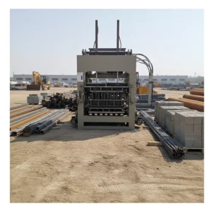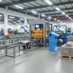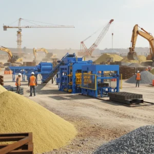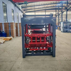
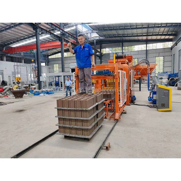
The Line as a System — A block press is only as productive as the slowest station feeding or clearing it, which is why this QT6-15 layout specifies every conveyor, mixer, and pallet handler between raw material intake and the curing rack, not just the machine in the middle.
Technical Specifications
| Parameter | Value |
|---|---|
| Product Type | Concrete Block Making Machine |
| Model | QT6-15 |
| Overall Dimensions (L×W×H) | 8200 × 1700 × 2950 mm |
| Total Mass | 7 T |
| Overall Power | 37 kW |
| Vibration Force | 45 kN |
| Vibration Frequency Range | 0 – 60 Hz |
| Vibration Form | Platform vibration |
| Moulding Mode | Automatic load, vibration moulding |
| Demolding Method | Hydraulic |
| Pallet Size | 880 × 850 mm |
| Molding Cycle | 15 – 20 s |
| Control System | PLC with touch screen |
| Hydraulic System | Independent integrated hydraulic station |
| Fault Diagnosis | Built-in system |
| Output Capacity (Hollow block 400×200×200mm) | 1,080 – 1,440 pcs/hour (basis: stated format and cycle) |
| Output Capacity (Solid brick 240×115×53mm) | 5,760 – 7,680 pcs/hour (basis: stated format and cycle) |
| Output Capacity (Rectangular paver 200×100×60mm) | 2,160 – 2,880 pcs/hour (basis: 20–25s cycle) |
| Factory Area (Minimum Recommended) | 1,200 m² |
Application Suitability
| Application | Material or Output |
|---|---|
| Hollow block production | 400×200×200mm and 400×150×200mm formats from crushed aggregate and cement |
| Solid brick production | 240×115×53mm standard format for load-bearing and partition walls |
| Paving block production | Rectangular 200×100×60mm and zigzag 225×112.5×60mm for external hardscape |
| Waste ash and slag utilization | Blended with reduced cement dosage for non-bearing and bearing block formats |
| On-site project production | Local aggregate sourcing for development and housing project contractors |
What a Cycle Time Figure Actually Means for Your Daily Output
A quoted cycle of 15 to 20 seconds is only achieved when the mixer, pallet feeder, and stacker all match that rhythm.
The press itself might be capable of completing a moulding cycle quickly, but if the upstream batching station takes 25 seconds to deliver a fresh charge, or the downstream pallet return loop is still clearing the last board, the press sits idle. Plant owners frequently size their investment around the fastest number on the spec sheet, then find the actual daily throughput settling at a lower figure dictated by the bottleneck station. This is why the QT6-15 block production line equipment is specified as a coordinated system, with each station’s throughput confirmed against the others before the line layout is drawn. [NEED_CITE: impact of station mismatch on block plant daily throughput]
Matching the Press Cycle to the Material Handling Loop
The QT6-15 completes a vibration moulding cycle in 15 to 20 seconds, meaning a fresh pallet must arrive at the press station, the moulded block must be pushed to the stacker, and the empty pallet must return — all within that same window. If any segment of this loop runs slower, the PLC will hold the next cycle. When we configure the pallet feeding and automatic stacking stations, we calculate the travel distance and conveyor speed so the physical movement completes before the press is ready for the next board. This is where a block plant either runs continuously or develops a visible stutter.
Sizing the Curing Area to the Pallet Specification
The 880 × 850 mm pallet size is not an arbitrary choice — it defines how many blocks move per cycle, how the curing racks are dimensioned, and what forklift mast width is required to load and unload them. If a buyer’s existing curing yard uses a different pallet footprint, the entire downstream handling sequence — from stacker to rack to cubing — must be re-specified. We confirm pallet dimensions and material against the buyer’s curing infrastructure before finalizing the QT6-15 block production line equipment layout, so no station is built around an assumption that breaks on day one of commissioning. [NEED_CITE: pallet size coordination between press and curing rack systems]
How Vibration Force and Hydraulic Pressure Shape Block Density
The platform vibration system delivers up to 45 kN across a 0 to 60 Hz range, working in tandem with the independent hydraulic station that controls demolding. These two forces must be balanced against the buyer’s specific mix design — the aggregate gradation, cement ratio, and moisture content all determine what vibration profile produces a consistent block with compressive strength exceeding 15 MPa. A line configured with the right vibration settings but fed by a mixer that delivers inconsistent batches will produce blocks of varying density, even if every other station is perfectly timed. The PLC touch screen allows the operator to store and recall vibration profiles for different block formats, reducing the guesswork when switching from hollow block to paver production.
The Cost of a Mismatched Supporting Line
When the raw material feeding system delivers a coarser blend than the mixer can homogenize within the cycle window, the press receives a charge that is unevenly distributed. The result is not a machine failure but a block quality failure — inconsistent weight, visible density variation, and compressive strength readings that scatter outside the acceptable band. Similarly, if the stacking station cannot clear moulded pallets fast enough, the operator is forced to pull blocks off by hand, negating the labour reduction the automation was purchased to deliver. These are the problems that do not appear in a factory test but surface during the first full production shift. [NEED_CITE: common causes of block density variation in new plant startups]
Why This Line Is Specified as One System
The QT6-15 block production line equipment is configured around the buyer’s local aggregate, target block format, and existing curing infrastructure, rather than quoted as a standalone press with optional add-ons. The machine, mould, pallet, and handling stations are matched as a set, with cycle time calculations stated per block format so the buyer knows what daily output to plan for. Mould design covers the formats the buyer’s market actually demands, including custom drawings when a standard catalogue mould does not fit the specification. The automation level is selectable — a buyer can begin with semi-automatic pallet handling and add the stacking and cubing stations later as production volume grows. [NEED_CITE: CE machinery directive requirements for industrial block production lines]
Documentation & Verification
- Line layout drawing with capacity calculation stated per block format, not a single aggregate figure
- Pallet specification sheet confirming dimensions, material, and load rating against the buyer’s curing rack
- Hydraulic and electrical schematic covering the full line, not the press station alone
- Voltage, frequency, and PLC display language confirmation signed off before production begins
- Factory test record run on the buyer’s target block format with cycle time logged per station
Installation, Commissioning & Support
- Foundation plan dimensioned to the 8200 × 1700 mm press footprint with vibration isolation specifications
- Dedicated 37 kW power circuit with voltage and frequency confirmed to local grid standards
- Line arrives in dismantled shipment configuration with station-by-station reassembly sequence documented
- On-site commissioning includes cycle time verification at each station against the original layout calculation
- Operator training covers PLC touch screen navigation, mould change procedure, and fault diagnosis response
- Wear parts list itemized by station with recommended replacement intervals for hydraulic and vibration components
What We Need to Configure Your Line
To move from an inquiry to a line layout, the first step is confirming the block formats your market sells and the daily volume you need to sustain. We also need the gradation and source of your local aggregate, the dimensions and forklift capacity of your curing area, and your local voltage and frequency standards. If you have existing mixers or material handling equipment that will remain in the line, send the specifications so we can calculate whether their cycle times match the QT6-15 press.
Frequently Asked Questions
Q: How is the daily output calculated, and which block format does it assume?
A: Each output figure on the specification sheet is tied to a specific block format and its corresponding moulding cycle. Hollow blocks at 400×200×200mm have a different cycle time than solid bricks or pavers, so the hourly and per-shift capacities differ accordingly. We provide a capacity calculation document that states the assumed format for each figure, so there is no single "maximum output" number floating without context.
Q: Which supporting equipment stations sit between the mixer and the curing rack?
A: Between the mixer discharge and the curing rack entrance, the line includes raw material feeding, pallet feeding, the press itself, wet block stacking, and pallet return. Each station’s cycle time is calculated so the press is never waiting for a pallet or a fresh charge. If any station is undersized, the bottleneck appears as press idle time, not as a visible machine fault.
Q: How does the 880 × 850 mm pallet size affect the downstream handling?
A: The pallet size defines the curing rack spacing, the forklift mast width needed to load racks, and the stacking station’s push mechanism. If your existing curing area uses a different pallet footprint, the entire downstream sequence must be reconfigured. We confirm pallet dimensions against your site infrastructure before the line layout is finalized to avoid a mismatch at commissioning.
Q: What factory area is required for the complete line?
A: The minimum recommended factory area is 1,200 square metres, which covers the raw material storage zone, the press and handling stations, the curing yard, and the finished block staging area. The actual footprint depends on how much curing inventory you need to hold at any given time and whether the cubing station feeds directly onto transport or into a separate warehouse bay.
Q: How are voltage and control language confirmed before shipment?
A: Voltage, frequency, and PLC display language are confirmed in writing during the quotation stage and again before production begins. This prevents a situation where the line arrives on site but cannot be powered or operated because the control interface is in an unsupported language or the motor winding does not match the local grid.