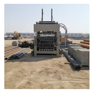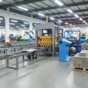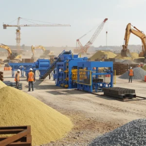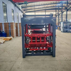
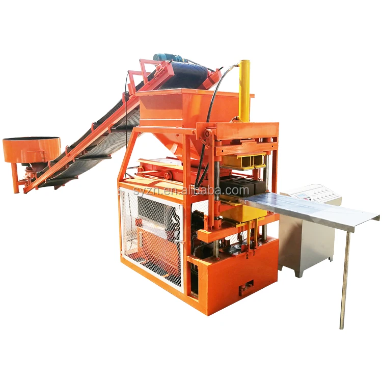
Cycle-matched line design — the LY2-10 clay interlocking block making machine production line is sized around a 10-second molding reference so upstream mixing and downstream pallet return never leave the press idle.
Technical Specifications
| Parameter | Value |
|---|---|
| Model | LY2-10 |
| Product Type | Clay Interlocking Block Making Machine |
| Rated Power | 7.5 kW |
| Molding Cycle | 10 s |
| Output Capacity | 6000 pcs / 8 hours (basis not stated in source — confirm block format, material, and thickness) |
| Output per Hour | 750 pcs (basis not stated in source — confirm block format, material, and thickness) |
| Raw Material Compatibility | Clay, soil, earth, mud, concrete, cement, fly ash |
| Block Size Option 1 | 300 × 150 × 100 mm |
| Block Size Option 2 | 250 × 125 × 75 mm |
| Block Size Option 3 | 230 × 220 × 115 mm |
| Pcs per Mould | 1 |
| Automation Level | Semi-automatic |
| Overall Dimensions | 1300 × 1800 × 2400 mm |
| Standards | CE (unit-level confirmation required) |
Application Suitability
| Application | Material or Output |
|---|---|
| Interlocking clay block production for housing projects | Local clay or soil stabilized with cement |
| Small plant earth block manufacturing | Earth and mud mixes with fly ash addition |
| On-site block production for infrastructure work | Concrete and cement blends using site aggregate |
| Format expansion for existing clay block producers | Multiple interlocking profiles on a single press |
Why the Press Alone Never Delivers the Quoted Output
A clay interlocking block making machine production line only meets its stated capacity when every station upstream and downstream is timed to the press cycle.
Buyers regularly receive quotations showing cycles per hour at the press with no mention of how raw material reaches the hopper or how wet blocks leave the pallet station. I have watched entire shifts lost because the mixer could not batch fast enough to keep the hopper charged, while the press sat idle between strokes [NEED_CITE: line bottleneck causes in block production]. The daily output then falls well short of what the brochure promised, and the buyer assumes the machine itself is underperforming.
Sizing the Mixer and Hopper to the 10-Second Cycle
The LY2-10 completes one molding stroke every 10 seconds, which sets the reference clock for the rest of the clay interlocking block making machine production line. The upstream mixer must deliver a fresh batch to the hopper within that window, or the press waits. Matching batch volume to the mold cavity charge ensures the hopper never runs dry between cycles.
Pallet Return Loop and Curing Area Coordination
Once the press releases a green block, the pallet must travel to the curing area and return before the next stroke. If the return distance or forklift cycle exceeds the 10-second interval, the press stalls. Planning the pallet circuit and curing rack layout around this timing keeps the line flowing without manual intervention at the semi-automatic stage [NEED_CITE: pallet handling impact on block line throughput].
Reading the Specification Sheet Against Local Conditions
The 7.5 kW rated power drives both the hydraulic ram and vibration system, yet actual block density depends on how well the mix design matches local clay or soil properties. A soil with high sand content behaves differently under pressure than one rich in silt. Confirming the raw material compatibility — clay, soil, earth, mud, concrete, cement, fly ash — against your actual source material avoids costly reformulation after the line is installed.
The Cost of Overlooking Station Synchronization
When line stations are sourced from separate suppliers without a unified cycle calculation, mismatches surface only during commissioning. A mixer that batches too slowly or a pallet conveyor that returns too late forces the operator to run the press in manual mode, negating the semi-automatic advantage. These delays compound across an eight-hour shift and erode the daily output the project schedule depends on [NEED_CITE: commissioning delays from mismatched line equipment].
What Sets This Line Configuration Apart
Block machinery remains the sole focus, so the LY2-10 press, mold, pallet, and handling equipment are specified as one matched system rather than assembled from separate vendors. Configuration is set against your actual mix design, local aggregate, and target block format instead of a catalogue default. Molds are designed for the interlocking profiles your market sells, including custom drawings when standard formats do not fit. The semi-automatic level allows a future automation upgrade without replacing the press itself. Installation and commissioning support includes operator training at your site.
Documentation & Verification
- Line layout drawing showing each station and the cycle time assumed at the press
- Machine specification sheet listing power, dimensions, and mold options for your format
- Pallet specification matched to your curing area and existing forklift capacity
- Voltage and control language confirmation recorded before production begins
- Factory test record run on your chosen block format before dispatch
- Wear parts and mold list supplied with the quotation for first replacement planning
Installation, Commissioning & Support
- Foundation pad sized to the 1300 × 1800 mm footprint with anchor bolt plan
- Dedicated 7.5 kW circuit with correct voltage and frequency confirmed before wiring
- Press arrives assembled; mixer and pallet stations bolt on during commissioning
- First production run sets molding cycle and pressure against your local clay mix
- Operator training covers mold change procedure for all three block size options
- Wear parts inventory covers initial operating period before first reorder
Preparing Your Line Inquiry
Share the interlocking block format you intend to produce, the daily volume your project requires, and the clay or soil characteristics at your site. Include your local voltage and frequency so the control panel can be configured before the line ships. If you already have a mixer or curing racks in place, provide their specifications so the new stations integrate without rework.
Frequently Asked Questions
Q: How is the line capacity calculated and which block format is it based on?
A: The stated output references the 10-second molding cycle at the press, but the actual daily volume depends on which of the three block size options you run and the material density. We provide a capacity calculation sheet that names the specific format, mix, and shift length so you can verify the number against your project target before ordering.
Q: Which supporting stations are included and which remain manual at this automation level?
A: At the semi-automatic level, raw material feeding and mixing are mechanized while pallet return and stacking involve manual steps. The quotation lists every station in the line so you see exactly where labor is needed and where a future automation upgrade can slot in without replacing the press.
Q: How do upstream mixer batch size and downstream pallet return time match the press cycle?
A: The mixer batch volume is calculated to refill the hopper within the 10-second cycle, and the pallet return path is laid out so a pallet reaches the press before the next stroke. Both values appear on the line layout drawing so you can confirm timing before the equipment is built.
Q: Can the line be upgraded from semi-automatic to higher automation later without replacing the press?
A: Yes. The LY2-10 press and its mold mounting interface remain unchanged when you add automatic pallet feeding or stacking stations later. The upgrade path is planned at the initial layout stage so structural and electrical provisions are already in place when you decide to expand.