
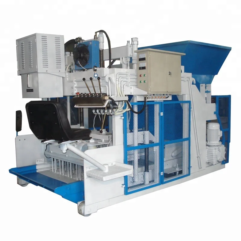
Single-Focus System Design — the QMY12-15 mobile egg laying block making machine production line is specified as one matched network of feeding, mixing, pressing, and curing logistics rather than a standalone press dropped onto an empty yard.
Technical Specifications
| Parameter | Value |
|---|---|
| Product Type | Mobile Egg Laying Block Making Machine |
| Model | QMY12-15 |
| Overall Dimensions (L×W×H) | 3250×2100×2300 mm |
| Total Mass | 4200 kg |
| Total Power | 16 kW |
| Hydraulic System Pressure | 16–20 MPa |
| Excitation Frequency | 3200 Hz |
| Vibration Mode | Three-dimensional mold vibration |
| Demold Method | Hydraulic |
| Moving Method | Automatic movement with hydraulic steering |
| Molding Cycle | 10–15 s |
| Output Capacity | 2880 pcs/h (based on 400×200×200 mm hollow block, 12 pcs/mould, 15–20 s cycle) |
| Output Capacity | 3360 pcs/h (based on 400×150×200 mm hollow block, 14 pcs/mould, 15–20 s cycle) |
| Output Capacity | 5280 pcs/h (based on 400×100×200 mm hollow block, 22 pcs/mould, 15–20 s cycle) |
| Daily Output | 23000 pcs/8 hr (based on 400×200×200 mm hollow block) |
| Block Compressive Strength | ≥15 MPa |
| Raw Materials | Fly ash, cinder, coal gangue, river sand, gravel, cement, industrial waste residue |
| Control System | PLC computer automatic control |
| Voltage & Frequency | Configurable to buyer’s local grid (to be confirmed before production) |
| Warranty | 1 year for the whole machine (excluding spare parts) |
Application Suitability
| Application Scenario | Typical Material or Output Focus |
|---|---|
| Temporary on-site hollow block production for housing projects | River sand, gravel, and cement mixed locally; 400×200×200 mm hollow blocks |
| Road infrastructure kerb and paving brick manufacturing | Crushed stone and fly ash blends; road kerb and interlocking paving formats |
| Small-to-medium block plant adding porous brick formats | Coal gangue or cinder aggregate with cement binder; porous brick and grassing brick |
| Remote construction site production without fixed plant foundation | Locally sourced industrial waste residue and cement; multiple block formats via mould change |
What "23,000 Blocks per Day" Leaves Out About Your Production Line
A capacity figure means nothing unless the upstream mixer, material feed, and curing yard can sustain the press rhythm without gaps.
When I visit sites where a mobile egg laying block making machine production line sits idle for minutes between cycles, the problem is almost never the press itself. The mixer batch takes too long to discharge, the raw material hopper starves, or the curing area is too small so the operator has to stop and move stacked blocks by hand before the machine can advance. I once saw a contractor in South Asia lose an entire shift because his wheel loader could not feed the mixer fast enough to keep up with the QMY12-15’s 10–15 second molding cycle. [NEED_CITE: material handling bottleneck analysis in mobile block production]
Positioning the Feed Station Around a Self-Propelled Press
The QMY12-15 relocates itself across the curing yard using hydraulic steering and automatic movement. This means the raw material feed station and mixer cannot sit in a fixed position relative to the press the way they would on a stationary line. The feed arrangement must cover the entire travel path, whether through a movable conveyor, a series of hopper drop points, or a loader-supported feeding routine that follows the machine as it lays blocks. If the material delivery falls behind the press travel speed, every molding cycle stretches past its rated 10–15 seconds and the daily output drops accordingly.
Matching Mixer Batch Time to the Molding Rhythm
A mobile egg laying block making machine production line lives or dies by whether fresh mix arrives at the hopper before the previous batch runs out. With the QMY12-15 producing up to 12 hollow blocks per cycle and cycling every 10–15 seconds, the mixer must deliver a consistent batch volume at intervals that prevent the press from waiting. If the mixer takes four minutes per batch but the press consumes that volume in two minutes, the line stalls. The mixer capacity, discharge speed, and water dosing rate must all be calculated against the target block format and the specific mix design your local aggregate allows. [NEED_CITE: batch cycle matching for continuous block production lines]
Reading the Pressure and Vibration Numbers Together
The hydraulic system pressure of 16–20 MPa and the excitation frequency of 3200 Hz do not operate independently — they work as a pair to compact the mix inside the mould cavity. Higher vibration frequency loosens the aggregate particles so they settle densely, while hydraulic pressure locks them into that compacted arrangement before demoulding. If your local aggregate is angular crushed stone rather than rounded river sand, the vibration force may need adjustment to achieve full compaction within the rated cycle time. A mismatch between these two parameters and your actual mix design produces blocks that crack during curing or fail compressive strength tests, regardless of how fast the press cycles.
When the Curing Yard Is Too Small for the Output
The QMY12-15 can produce up to 23,000 hollow blocks of 400×200×200 mm format in an eight-hour shift. Every one of those blocks sits on the ground where it was laid and occupies curing space for days before it can be moved. If the curing yard is not sized for multiple days of accumulated output, the machine operator must eventually stop the press because there is nowhere left to lay blocks. This is the most common line-balancing failure on mobile egg laying block making machine production line installations — the buyer plans for the press footprint but not for the curing area that the press output demands. [NEED_CITE: curing yard area calculation for egg laying block machines]
Why We Configure the Line, Not Just the Press
Block machinery is our single focus, so every component from the raw material feeder through the mixer to the curing logistics is specified as one system matched to the QMY12-15’s cycle time. We set the configuration against your actual mix design and local aggregate rather than a catalogue default, because I have watched a line in West Africa shut down for two weeks when volcanic aggregate responded differently to the standard vibration settings. Mould design covers the formats your market actually sells, with custom drawings available. The automation level is selectable so you can start with manual material handling and add feeding equipment later. Installation support includes operator training on your specific line arrangement.
Documentation & Verification
- Line layout showing mixer placement, feed path, and curing yard dimensions for the QMY12-15 travel range
- Capacity calculation sheet stating which block format and mould cavity count each output figure assumes
- Machine specification sheet covering hydraulic pressure, vibration frequency, and total power draw
- Mould drawing and format list confirming every block type your market requires
- Voltage and PLC display language confirmation signed off before production begins
- Factory test record and packing photographs provided before container loading
Installation, Commissioning & Support
- Curing yard must accommodate 3250×2100 mm machine footprint plus multi-day block storage area
- 16 kW total power requires dedicated circuit with confirmed voltage and frequency matching local grid
- Machine ships assembled; hydraulic steering and movement systems tested before dispatch
- First-day commissioning includes vibration frequency and hydraulic pressure calibration against your mix
- Operator training covers mould change procedure and daily maintenance of hydraulic demould components
- Wear parts and mould list provided for ongoing supply from day one
What to Include in Your Inquiry
To configure the QMY12-15 within a complete mobile egg laying block making machine production line, we need your target block formats with dimensions, your daily output target per format, the type and gradation of aggregate available at your site, and the total curing yard area you can allocate. Provide your local voltage and frequency so the electrical system is built correctly before the machine leaves the factory.
Frequently Asked Questions
Q: How do I verify the daily output figure for my specific block format?
A: The output capacity changes with every block format because mould cavity count and cycle time differ. A 400×200×200 mm hollow block runs 12 pieces per mould, while a 400×100×200 mm format runs 22 pieces per mould. Ask for a capacity calculation that states the exact format, cavity count, and cycle time assumed, then compare that against your actual mix setting time.
Q: How should I size the mixer and material feed system around this press?
A: The mixer must deliver each batch before the QMY12-15 consumes the previous one. With a 10–15 second molding cycle, calculate how many blocks each batch produces, then match mixer discharge time to that consumption rate. The feed system must also cover the machine’s full travel path across the curing yard.
Q: What happens if my local voltage does not match the machine specification?
A: Voltage and frequency mismatches cause motor overheating, PLC faults, or outright failure on first startup. These parameters must be confirmed before production begins. Provide your site’s exact voltage, phase configuration, and frequency so the electrical system is built to match.
Q: How much curing yard area do I need for the QMY12-15 output?
A: Each day’s production of up to 23,000 hollow blocks (400×200×200 mm format) remains on the ground until cured. Multiply the single block footprint by daily output and then by the number of curing days your climate requires. The yard must hold several days of accumulated output before any blocks are moved to storage.
Q: Can the supporting equipment be added in stages after the initial purchase?
A: The QMY12-15 can start with manual material handling and a basic mixer, then add automated feeding and batching equipment later. The machine’s PLC control system accommodates additional stations as they are connected. Confirm the upgrade path during initial configuration so electrical and hydraulic interfaces are pre-installed.


