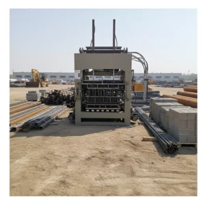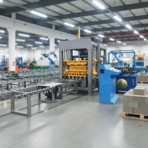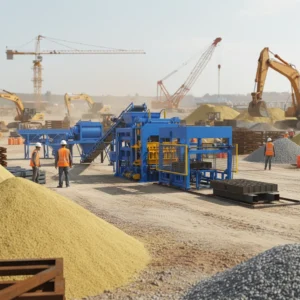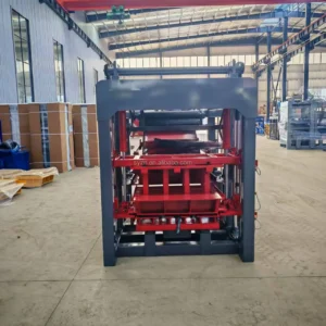
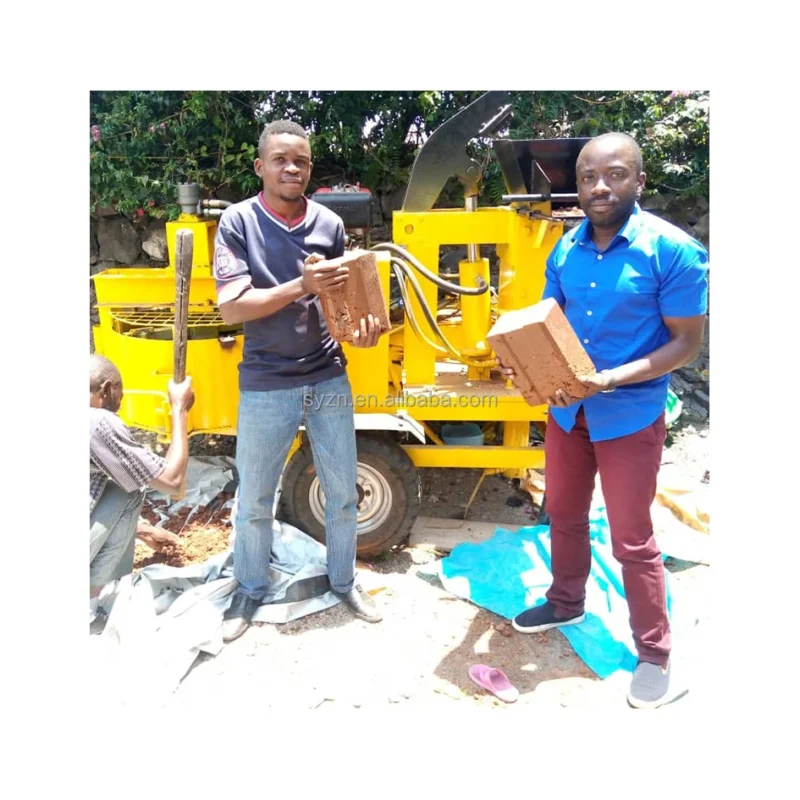
Matched System Design — We specify the M7MI hydraulic clay block press alongside every supporting station, calculating cycle times per format so the line runs without idle gaps.
Technical Specifications
| Parameter | Value |
|---|---|
| Model | M7MI |
| Product Type | Hydraulic Clay Interlocking Block Making Machine |
| Overall Dimensions (L×W×H) | 3200×1100×1500 mm |
| Net Weight | 1100 kg |
| Power Source | Diesel Engine |
| Hydraulic Pressure | 16 MPa |
| Moulding Cycle | 15–20 s |
| Productivity Example | 300×150×100 mm interlocking block, 20 s cycle, 1 pc/mould, 1600 pcs/8 hr (basis to be confirmed) |
| Raw Material Compatibility | Clay, soil, concrete |
| Mould System | Interchangeable moulds for multiple interlocking block formats |
| Control System | Manual / semi-automatic operation (basis to be confirmed) |
| Voltage & Frequency | Not applicable (diesel-powered main press) |
| Key Features | Diesel engine independence, interchangeable mould system, hydraulic interlocking block forming |
Application Suitability
| Application | Material or Output |
|---|---|
| Remote housing project block production | Locally sourced clay and soil mixed with stabilizers |
| On-site interlocking wall construction | Soil-cement mixes for load-bearing interlocking profiles |
| Small-scale regional block supply | Concrete blends for paving and structural interlocking blocks |
| Off-grid development sites | Any compatible mix design where grid electricity is unavailable |
Why the Mixer Matters More Than the Press Cycle
A block machine is only as fast as the slowest station feeding it.
I once watched a buyer in West Africa run a clay brick line where the press cycled every twenty seconds but the mixer took nearly a minute per batch. The operator spent half the shift standing idle, and the daily count fell well below what the quotation promised. The hydraulic clay block making machine production line only delivers its rated output when raw material feeding, mixing, moulding, and pallet handling are timed as one sequence — not purchased as separate afterthoughts [NEED_CITE: production line cycle synchronization principles for block manufacturing].
Raw Material Feeding and Mixing Station Alignment
The M7MI completes a moulding stroke every 15 to 20 seconds, which means the mixer must deliver a fresh batch of clay or soil-cement mix on that same cadence. A hydraulic clay block making machine production line built around this press needs a pan mixer or shaft mixer sized to match, with a feeding hopper positioned so the operator or conveyor bridges the gap without manual shoveling. When the mixer falls behind, the press sits idle and the daily throughput collapses regardless of how fast the hydraulic ram can cycle.
Pallet Handling and Curing Area Configuration
Interlocking blocks formed on the M7MI must be transferred to a curing zone while the mix is still green. If pallet size is chosen without checking the buyer’s existing forklift fork width or curing rack dimensions, pallets pile up on the floor and handling becomes a bottleneck. The hydraulic clay block making machine production line should specify pallet material — timber, bamboo, or composite — alongside the curing area footprint so blocks can be moved, stacked, and retrieved without breakage or double-handling [NEED_CITE: pallet specification standards for concrete block curing].
Interpreting Hydraulic Pressure and Moulding Cycle for Clay Mixes
The 16 MPa hydraulic pressure on the M7MI is calibrated for clay, soil, and concrete blends typical of interlocking block production. Higher pressure compresses the mix more densely, but if the clay moisture content is too high, excess pressure simply squeezes water out and weakens the green block. The 15–20 second moulding cycle gives the hydraulic ram enough dwell time to consolidate soil-cement mixes thoroughly, though very stiff concrete blends may require the longer end of that range. Interchangeable moulds allow the operator to switch between interlocking profiles, but each format change also means re-verifying that the new cavity depth and mix volume still align with the press stroke and hydraulic pressure setting.
What Happens When Supporting Equipment Is Left Out of the Quotation
Buyers who receive a press-only quotation often discover after delivery that pallets must be fed by hand, mixed material must be shoveled into the hopper, and finished blocks must be carried to the curing area one pallet at a time. The daily output number on the invoice assumed a fully supported line, but the actual throughput depends entirely on how many workers are assigned to manual handling. Labour costs climb, operator fatigue sets in, and block quality varies because the rhythm of the hydraulic clay block making machine production line is dictated by human speed rather than mechanical timing [NEED_CITE: manual versus mechanized block production throughput comparison].
Why Source the Full Line from One Supplier
We treat block machinery as a single discipline rather than assembling a line from separate equipment vendors. The M7MI press, moulds, pallets, and supporting handling stations are specified together so cycle times align from feeding through curing. Configuration is set against the buyer’s actual clay or soil mix and the interlocking block format their market requires, not a catalogue default. Mould drawings cover every profile the buyer plans to produce, including custom formats built to buyer-supplied dimensions. Automation level is selectable, so a buyer can begin with manual pallet handling and add mechanized stacking later. Installation support includes operator training on the complete line, and wear parts lists are provided before the first replacement is due.
Documentation & Verification
- Line layout drawing showing each station position and material flow path for the M7MI configuration
- Capacity calculation sheet stating the interlocking block format and mix design assumed for output figures
- Mould drawing package listing every interlocking profile with cavity dimensions and changeover procedure
- Hydraulic and electrical schematic covering the 16 MPa system and any auxiliary electric stations
- Factory test record documenting press cycle timing and block sample results before dispatch
- Operation and maintenance manual covering daily, weekly, and monthly service intervals for the full line
Installation, Commissioning & Support
- Foundation pad sized to the M7MI footprint of 3200×1100 mm with anchor bolt pattern marked on layout drawing
- Diesel engine service schedule provided alongside commissioning checklist for first-run hydraulic pressure verification at 16 MPa
- Auxiliary electric stations such as the mixer wired to local voltage and frequency confirmed before shipment
- Mould changeover procedure trained on-site so operators can switch interlocking profiles within one shift segment
- Wear parts list covering hydraulic seals, mould liners, and pallet surfaces with recommended reorder intervals
- Curing rack layout matched to pallet dimensions and buyer’s forklift capacity to avoid double-handling
Before You Request a Quotation
To build a line layout that actually matches your project timeline, we need your target interlocking block format and dimensions, the clay or soil-cement mix design you plan to use, and your available curing area footprint. Let us also know whether auxiliary stations like the mixer will run on local grid power or require a generator, and what forklift or handling equipment you already have on site.
Frequently Asked Questions
Q: How is the daily output of the M7MI calculated and which block format does it assume?
A: The productivity example of 1,600 pieces per 8-hour shift is based on a 300×150×100 mm interlocking block with a 20-second cycle producing one piece per mould stroke. Different interlocking formats with larger or smaller cavity volumes will change the cycle time and pieces-per-stroke count. Always confirm which block format the quoted output assumes before comparing machines.
Q: Which supporting equipment stations are included so the press is not left idle between cycles?
A: A complete line configuration covers raw material feeding, mixing, pallet feeding, and curing rack handling alongside the M7MI press. Each station’s cycle time is calculated to match the 15–20 second moulding stroke so material and pallets arrive before the press is ready for the next cycle. The exact scope depends on the automation level selected.
Q: How does the diesel engine integrate with electric auxiliary stations such as the mixer?
A: The M7MI main press runs entirely on its diesel engine, making it independent of grid electricity. Auxiliary stations like the mixer and any conveyor feeders typically require electric power, which can be supplied by a local grid connection or a standalone generator sized to their combined kW draw.
Q: What clay or soil mix properties are required for the 16 MPa hydraulic pressure?
A: The 16 MPa pressure is suited to clay and soil-cement blends with moisture content controlled to allow compaction without excess water bleed. A mix that is too wet will extrude from the mould edges, while one that is too dry will not consolidate fully. We recommend testing your local material with a sample batch before finalizing the line configuration.
Q: How is pallet size selected to match the curing area and forklift on site?
A: Pallet dimensions are chosen based on the mould footprint and the curing rack spacing available at your site. The pallet material and thickness must also match the forklift fork width and load capacity already in use. Confirming these details before production prevents pallets that cannot be stacked or moved efficiently.