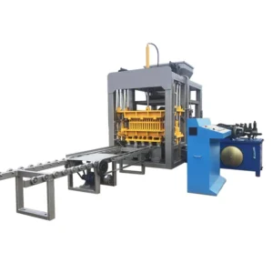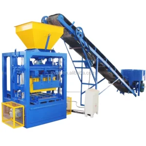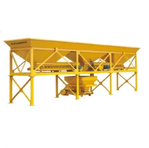
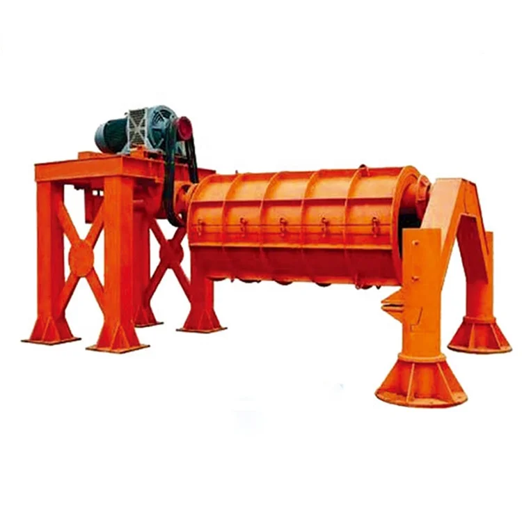
Matched Line Engineering — the roller forming station, pipe moulds, feeding and curing handling specified together so cycle times align from raw material intake to final stacking, not sourced as disconnected islands.
Technical Specifications
| Parameter | Value |
|---|---|
| Product Type | Suspension Roller Concrete Pipe Making Machine |
| Machine Type | Suspension Roller type |
| Pipe Diameter Range | 300–2500 mm |
| Pipe Length Range | 2–4 meters |
| Pipe Joint Types | Flush joint, Socket & spigot joint |
| Forming Method | Centrifugal force and roller compaction |
| Material Type | Dry cast concrete |
| Cycle Time | 3–5 minutes per pipe (basis not stated in source — confirm pipe diameter / wall thickness / concrete mix) |
| Mould Type | Customized concrete pipe mould |
| Noise Level | 80–90 dB |
| Voltage & Frequency | Configurable to buyer’s site supply (confirm before order) |
| Control System | Available with PLC or relay logic based on automation preference |
Application Suitability
| Application | Material or Output |
|---|---|
| Municipal drainage pipe plants | Reinforced concrete pipes in socket & spigot joint for gravity sewer lines |
| Agricultural field irrigation networks | Dry cast concrete pipes in flush joint for open channel and low-pressure delivery |
| Road culvert fabrication | Large-diameter reinforced pipes up to 2500 mm for highway cross-drainage |
| Pre-stressed concrete pipe manufacturers | Pre-stressed cylinder pipe cores before wire winding and coating stages |
| Deep water well casing | Socket joint pipes sized to borehole diameter requirements |
What "3 Minutes per Pipe" Actually Depends On
A cycle time is only honest when the pipe format, wall thickness and mix design are named beside it.
I once watched a concrete pipe making machine production line in Kenya stall for an entire morning because the supplier had quoted a three-minute cycle on a 400 mm pipe, while the buyer’s daily target was all 1200 mm drainage culvert. The roller compaction force that works on a thin-walled small pipe simply does not transfer the same energy into a heavy-walled large format. Without adjusting the roller pressure, centrifugal speed and feed rate to the actual diameter and mix being run, the concrete either segregates or leaves voids in the wall. [NEED_CITE: concrete pipe forming standards for wall density and compaction requirements]
How Stations Connect Across the Pipe Line
A concrete pipe making machine production line is only as fast as its slowest handoff. The raw material feeding system must deliver a consistent batch weight to the mixer within the same window that the roller station finishes compacting the previous pipe. If the mixer discharge lags, the forming station sits idle; if it runs ahead, fresh concrete waits in the hopper and begins losing workability. Matching these intervals is the reason line layout matters more than any single station’s rated speed.
Where Roller Forming Meets Dry Cast Reality
The suspension roller method compacts dry cast concrete against the inner wall of a rotating mould through centrifugal force and direct roller pressure. This produces a dense pipe wall with no waste cement slurry, which matters in regions where cement cost dominates the unit economics. The dry cast process also means pipes can be demoulded sooner than wet cast equivalents, allowing the same mould to cycle again within the shift. However, the moisture content of the aggregate must stay within a narrow band — too dry and the concrete will not consolidate under the roller, too wet and the pipe slumps when the mould opens. [NEED_CITE: dry cast concrete pipe moisture tolerance ranges]
Reading the Specs That Shape Daily Output
The pipe diameter range of 300–2500 mm tells a buyer which market segments the line can serve, but the real constraint is how many moulds the buyer can afford to keep in rotation. Each pipe stays in its mould during initial curing, so a plant running 1200 mm drainage pipe might need dozens of moulds to keep the roller station busy across a full shift. The pipe length range of 2–4 meters further multiplies the mould inventory decision, since a 4-meter mould costs more and takes longer to fill than a 2-meter one in the same diameter. Joint type selection — flush versus socket and spigot — affects both mould complexity and the demoulding sequence, with socket joints requiring an extra collar ring that adds to mould change time. The noise level of 80–90 dB means the forming station needs acoustic separation from any manual packing area nearby, or operators will require hearing protection across the full shift.
The Cost of Skipping the Line Layout Step
When a buyer purchases the roller forming machine alone and sources the mixer, pallet conveyor and curing racks from separate vendors, the handoff points become the failure zones. I have visited plants where the overhead crane could not lift a fully loaded 2500 mm mould fast enough to clear the station before the next feed cycle began, forcing the operator to hold the feeder and waste minutes every pipe. Another site had a curing yard designed for 2-meter pipes but ordered 4-meter moulds, leaving half the pipe length resting on bare ground during early cure. These mismatches do not show up in any single equipment quotation — they appear only after the line is bolted down. [NEED_CITE: industrial plant layout coordination for concrete product lines]
Why Buyers Place Repeat Orders Here
Every line we ship leaves with a station-by-station capacity sheet that names the pipe format used for each calculation, so the buyer sees where the bottleneck sits before the containers are loaded. Mould drawings are reviewed against the buyer’s joint specification and local gasket standard before steel is cut, preventing the socket collar mismatch that would otherwise surface during commissioning. The raw material feeding and mixer are sized to the roller station’s actual fill volume per cycle, not to a generic throughput figure. Voltage, frequency and control language are confirmed in writing before assembly begins, which avoids the two-week delay I once saw in Tanzania when a control panel arrived with Chinese-language labels and a 380 V bus that did not match the site transformer. Documentation, wear parts lists and mould maintenance schedules travel with the machine so the first replacement order can be placed without reverse-engineering the original.
Documentation & Verification
- Line layout drawing showing each station footprint and pipe flow direction for your diameter range
- Capacity calculation sheet stating the pipe format and wall thickness assumed per cycle
- Mould drawing with joint type detail and dimensional tolerances before fabrication
- Voltage, frequency and PLC display language confirmation signed before assembly
- Factory test record on your specified pipe diameter before container loading
- Operation and maintenance manual with mould inspection intervals and roller wear limits
Installation, Commissioning & Support
- Foundation plan sized to the roller station’s operating weight and vibration profile for your pipe diameter range
- Power supply spec listing the amperage and dedicated circuit requirement for the forming station motor
- Mould assembly sequence and roller gap adjustment procedure for each pipe diameter in your range
- First-run protocol covering feed rate, roller pressure and centrifugal speed setting for your local aggregate
- Operator training on joint collar changeover and demoulding sequence for flush and socket formats
- Wear parts list covering roller surface, mould lining and drive bearings with reorder intervals
What to Include with Your Inquiry
Send the pipe diameters and joint types your market actually orders, along with the wall thickness your local drainage or irrigation standard requires. Include the aggregate type and cement grade available near your site so the mix can be validated before the line is configured. Confirm the site voltage, frequency and the language your operators will need on the control display.
Frequently Asked Questions
Q: How is realistic daily capacity confirmed for my pipe format?
A: We build a station-by-station timing sheet based on the pipe diameter, wall thickness and mix design you will actually run. Each handoff — mixing, feeding, forming, demoulding and curing transfer — is listed with its cycle contribution, so you see the true bottleneck before committing.
Q: What happens if my site voltage does not match the motor rating?
A: Voltage and frequency are confirmed before the electrical panel is built. If your site supply differs from standard industrial ratings, the motor and control components are sourced to match your transformer output, preventing commissioning delays.
Q: How do you match upstream feeding to the roller forming cycle?
A: The mixer batch size and conveyor feed rate are calculated from the roller station’s fill volume per pipe. This ensures fresh concrete arrives exactly when the previous pipe finishes compaction, without the mix waiting in the hopper and losing workability.
Q: What support is provided during first production runs?
A: Our technician sets roller pressure, centrifugal speed and feed timing to your local aggregate and cement during on-site commissioning. Operators are trained on mould changeover, joint collar handling and daily roller inspection before handover.