
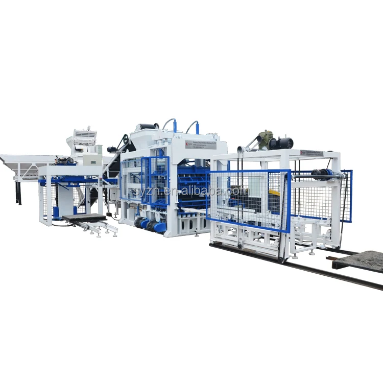
Matched System Engineering — the QT10-15 press is specified alongside its mixing, pallet feed and stacking stations so the line runs at cycle tempo without idle gaps.
Technical Specifications
| Parameter | Value |
|---|---|
| Model | QT10-15 |
| Product Type | Stationary Fully Automatic Hydraulic Concrete Block Making Machine |
| Control System | PLC control cabinet |
| Hydraulic System | Independent integrated hydraulic station |
| Vibration Mode | Vertical station mode resonance, automatic FM-AM tuning |
| Automation Level | Fully automatic |
| Pallet Feed | Pallet feed machine included |
| Material Handling | Storage hopper and conveyor included |
| Output: 400×200×200mm hollow block | 1,800–2,400 pcs/h (14,400–19,200 pcs per 8-hour shift) |
| Output: 400×150×200mm hollow block | 2,160–2,880 pcs/h (17,280–23,040 pcs per 8-hour shift) |
| Output: 240×115×53mm standard brick | 8,928–11,160 pcs/h (71,424–89,280 pcs per 8-hour shift) |
| Output: 200×100×60mm paving block | 5,184–6,480 pcs/h (41,472–51,840 pcs per 8-hour shift) |
| Output: 225×112.5×60mm interlocking block | 4,032–5,040 pcs/h (32,256–40,320 pcs per 8-hour shift) |
| Cycle Time: 400×200×200mm & 400×150×200mm | 15–20s |
| Cycle Time: 240×115×53mm | 15–20s |
| Cycle Time: 200×100×60mm & 225×112.5×60mm | 20–25s |
| Moulds per Cycle: 400×200×200mm | 10 pcs |
| Moulds per Cycle: 400×150×200mm | 12 pcs |
| Moulds per Cycle: 240×115×53mm | 62 pcs |
| Moulds per Cycle: 200×100×60mm | 27 pcs |
| Moulds per Cycle: 225×112.5×60mm | 24 pcs |
| Mould Change | Simple replacement for multi-format production |
| Warranty | 1 year for whole machine (excluding spare parts) |
| Rated Power (kW) | (basis to be confirmed) |
| Voltage & Frequency | (basis to be confirmed) |
| Overall Dimensions | (basis to be confirmed) |
| Net Weight | (basis to be confirmed) |
| Pallet Size | (basis to be confirmed) |
Application Suitability
| Application | Material or Output |
|---|---|
| High-capacity hollow block production | Crushed stone, sand, cement and fly ash mixes |
| Standard solid brick manufacturing | River sand, stone dust and cement blends |
| Paving block runs for roads and walkways | Granite aggregate and cement at high compaction |
| Interlocking block production for landscaping | Graded aggregate with pigment for colour layers |
| Multi-cellular brick runs for wall systems | Lightweight aggregate or expanded clay mixes |
| Stationary block plant setups for housing projects | Local aggregate matched to regional strength specs |
Why the Mixer Must Match the Press Tempo
A faster press starved by a slow mixer is just an expensive idle machine.
I once watched a plant in West Africa run a large stationary press with an undersized pan mixer upstream. The press was ready for the next cycle every twenty seconds, but the mixer needed thirty-five seconds to discharge a full batch. The operator stood by the control cabinet watching the press wait. Over an eight-hour shift, those missing seconds added up to tens of thousands of blocks that never left the line. The stationary block making machine production line only delivers its rated output when every station — feeding, mixing, pressing, pallet handling, stacking — runs at the same tempo. [NEED_CITE: typical block plant cycle matching principles]
From Raw Feed to Cured Stack — The Complete Line
A stationary block making machine production line is only as reliable as its weakest connection. The QT10-15 sits at the centre of a sequence that begins with the storage hopper and conveyor feeding raw material into the mixer, continues through the pallet feed machine delivering boards to the press at every cycle, and finishes with automatic stacking moving freshly pressed blocks to the curing area. If any one of these stations runs slow, the press waits and daily output drops below the calculation you planned on.
Where Cycle Time Gaps Appear
The press itself cycles between 15 and 25 seconds depending on block format. Upstream, the mixer discharge and conveyor travel must complete within that same window. Downstream, the pallet feed machine has to slide a fresh board into position before the next press stroke, and the stacking station must clear the finished pallet before the new one arrives. I have seen lines where the pallet return conveyor was too slow, creating a queue that forced the PLC to hold the press. Mapping each station’s cycle against the QT10-15 rhythm is how the stationary block making machine production line earns its output figures. [NEED_CITE: material flow matching in automated concrete plants]
Reading the Spec Sheet Against Your Actual Product
The output table above lists five block formats, each with its own cycle time, mould cavity count and shift capacity. Those figures only hold when the mix design, aggregate grading and compaction pressure are set for that specific format. A 400×200×200mm hollow block at ten pieces per cycle and a 15–20 second stroke yields 1,800–2,400 pieces per hour. Switch the mould to 240×115×53mm standard bricks at 62 pieces per cycle, and the hourly figure jumps — but the mixer must now deliver a higher volume of finer mix per stroke. The independent integrated hydraulic station keeps pressure stable across these format changes because it sits away from the main vibration frame, and the vertical station mode resonance with automatic FM-AM tuning adjusts vibration frequency without manual dial-in each time a new mould goes on.
What Happens When Line Stations Are Sourced Separately
I visited a site where the owner bought the press from one supplier, the mixer from another, and the pallet handling from a third. The pallet size the handling system accepted was twenty millimetres shorter than what the QT10-15 frame required. The fix was a set of adapter rails fabricated on site, but for the first three weeks the line ran at roughly two-thirds of its capacity. When pallet feed, conveyor, stacking and curing rack handling are specified together with the press, the pallet dimensions, fork slots and curing rack spacing all align with the block formats the mould produces. That is the difference between a stationary block making machine production line that runs from day one and one that needs a month of field adjustments. [NEED_CITE: pallet specification alignment in block making lines]
Why We Configure the Line, Not Just the Press
Every line we ship starts with the buyer’s target block format, local aggregate sample and daily output requirement. The machine, mould, pallet and handling equipment are specified as one matched system, not assembled from separate catalogue pages. The configuration is set against the buyer’s actual mix design — not a default that assumes material the buyer cannot source locally. Mould design covers the formats the buyer’s market actually sells, including custom drawings when a regional standard falls outside the normal range. The automation level is selectable, so a buyer can commission the QT10-15 in semi-automatic mode and add automatic stacking later without replacing the press. Installation includes on-site commissioning with operator training so the crew knows how to read the PLC display, swap moulds and run the daily maintenance checklist before the service team leaves the site.
Documentation & Verification
- Line layout drawing showing station spacing and capacity per block format for the QT10-15
- Machine specification sheet listing hydraulic pressure, vibration force and pallet size matched to your mix
- Mould drawing and format list confirming cavity count and cycle time for each block type ordered
- Voltage, frequency and PLC display language confirmation document signed before production starts
- Factory test record on your specified block format before the press is dismantled for shipment
- Wear parts and mould list with part numbers so first replacements are on order before you need them
Installation, Commissioning & Support
- Foundation plan specifying load points and curing area dimensions matched to the QT10-15 pallet size
- Dedicated power circuit sized to the press rated load, confirmed against your local voltage and frequency
- Machine dismantled into container-load sections with reassembly sequence documented in the manual
- First-cycle parameter setting on your aggregate and mix design during on-site commissioning
- Operator training covering PLC navigation, mould change procedure and daily hydraulic checks
- Spare parts kit covering seals, vibration springs and hydraulic hoses for the first year of production
Before You Request a Quote
Send us your target block formats, required daily output per format, and a sample description of your local aggregate and cement type. We also need your site voltage and frequency, preferred PLC display language, and the dimensions of your existing curing area and forklift capacity if you plan to integrate the new line with current handling equipment. With those details the stationary block making machine production line proposal can state a verified output figure for every block size you intend to produce.
Frequently Asked Questions
Q: How is the capacity of the QT10-15 verified, and which block format does each output figure assume?
A: Every capacity figure in the specification table is tied to a named block dimension, mould cavity count and cycle time range. The 1,800–2,400 pieces per hour figure, for example, assumes a 400×200×200mm hollow block at ten cavities and a 15–20 second cycle. When you share your target format, we recalculate the line output based on that specific mould and cycle setting.
Q: How do the press cycle times match with upstream mixing and downstream pallet stacking?
A: We map every station’s cycle — mixer discharge, conveyor travel, pallet feed, press stroke, stacking removal — against the QT10-15 cycle time for your chosen block format. If any station falls outside the press window, we resize that component before the line is built, so the press never waits for material or pallet clearance during a shift.
Q: What voltage, frequency and PLC language options need to be confirmed before production?
A: We need your site supply voltage, frequency and phase written on the order confirmation, along with the language you want on the PLC display. These parameters are locked before the electrical cabinet is wired, avoiding rework or delayed commissioning after the machine arrives at your plant.
Q: How is the hydraulic system configured to handle dust and vibration in a block plant?
A: The QT10-15 uses an independent integrated hydraulic station mounted away from the main vibration frame. This isolation reduces the transfer of shock and concrete dust into hydraulic valves and hoses, maintaining consistent pressure across continuous shift operation and extending the service interval for seals and filters.
Q: What supporting equipment is included in the line quotation versus sourced separately?
A: The quotation covers the press, PLC cabinet, hydraulic station, pallet feed machine, storage hopper and conveyor. Stacking systems, curing rack handling and cubing equipment are specified to match the line but can be included or excluded based on your existing plant setup. Each item is listed separately so you see exactly what is in the shipment.


